
A custom light can meet its drawing dimensions yet leave too little gap at the finished ceiling. To prevent that mismatch, review the complete installed interface: the smallest opening, largest finished fixture envelope, relative center position and usable adjustment. Compare the resulting minimum clearance with what the project actually needs for assembly, appearance and access. The worksheet and illustrative calculation below help designers coordinate those inputs with the manufacturer and site team; they do not prescribe universal lighting tolerances or replace structural and electrical design.
A Lighting Fixture Can Be Within Tolerance and Still Not Fit
The gap belongs to an interface, not to either component alone. Opening size, fixture size and center position can each vary within their agreed limits, while their combined effect leaves insufficient space on one side. A tolerance stack-up is the combined effect of dimensional variation on a relationship such as the clearance between a finished lighting assembly and its surrounding opening. Check that relationship before treating individually compliant parts as evidence of installed fit.
Nominal dimensions describe the intended geometry. Tolerances describe permitted departures from it. A drawing that shows a generous-looking gap may therefore represent only the centered, nominal condition. The installation problem appears when a smaller opening meets a larger fixture and the suspension position shifts toward an edge.
Begin with the function of the gap. A visible shadow line, space for fitting a canopy and access for removing a glass element are different needs. Record the relevant project criterion beside the dimension rather than assuming that any positive clearance is sufficient. For broader input preparation, the lighting specification resources provide related guidance.
The practical question is not whether every dimension should be tighter. It is which dimension or position controls the limiting relationship. Tightening an unrelated frame detail cannot correct a ceiling opening built in the wrong location.
- Define the finished opening, finished fixture envelope and shared location reference.
- Calculate the smallest side gap using size limits and relative center offset, without double-counting included variation.
- Compare that gap with the project’s functional need, then verify any approved correction.
Define the Finished Reference Before Allocating Tolerances
Agree on the finished opening and a shared reference before comparing dimensions. A datum is an agreed reference from which a dimension or position is measured. For a lighting interface, the team needs to distinguish the opening’s width, the fixture’s outer envelope and the position of their centers. All three can be correct on separate drawings yet incompatible if the drawings use different references.
Formal drawing language helps remove that ambiguity. ASME Y14.5 provides conventions for stating and interpreting geometric dimensioning and tolerancing on drawings and models. Its published scope does not supply a ready-made tolerance for your chandelier or ceiling; the appropriate controls still depend on the interface being designed.
Identify whether the site dimension refers to structural concrete, an unfinished recess, the finished ceiling face or the final decorative trim. A dimension to an unfinished edge cannot simply be substituted for the clear finished opening. The site team should also identify which reference survives finishing and remains accessible during installation.
Keep vertical and horizontal references explicit. Record the finished ceiling level for the installed drop, the finished floor level for the lowest point and the agreed location reference for suspension coordinates. If the fixture follows a sloping or curved ceiling, ask for the relevant sections rather than reducing the whole interface to one width and one height.
Trace the Variation Through the Lighting Assembly
Trace the actual dimension path from the site reference through the mounting assembly to the outermost lighting component. Add each contributor once. If the specified overall envelope already includes the frame, glass and finish, adding their full tolerances again would double-count variation. If only the bare frame is specified, those omitted contributors still need to be evaluated.
Kinglong Lighting’s custom-development process describes blueprint review, modeling and sample approval. Use that development discussion to clarify which dimensions describe individual components and which describe the assembled product. A visual sample and a dimensioned assembly answer different questions; ask for the interface evidence that your ceiling coordination requires.
Canopy, Frame and Glass: Control the Outermost Envelope
Check the finished canopy, frame and glass in their assembled state. The controlling width may belong to a glass edge, projecting fastener or decorative element rather than the metal frame. For a canopy, distinguish the concealed part that enters an opening from the visible part intended to cover it. One can have enough overlap while the other has insufficient insertion clearance.
Identify the measurement stage. A dimension before coating or assembly is not automatically the finished dimension. Ask how glass seating, connection play and finish build are included in the quoted envelope. For repeated pieces, review the limiting orientation and assembly position rather than measuring whichever face happens to be easiest to reach.
Measurement conditions also matter when margins are tight. NIST’s dimensional-metrology guidance explains temperature effects and thermal-expansion corrections. Record conditions where they affect the comparison; that metrology guidance is not an instruction to hold every jobsite at a laboratory temperature. Operating-temperature movement, where relevant, needs its own engineering assessment.
Suspension and Ceiling: Separate Height From Position
The total installed drop depends on the suspension, mounting arrangement and lowest decorative element, measured from the defined finished ceiling reference. Review that vertical chain separately from lateral positioning. A cable-length adjustment may correct height, but it does not necessarily move a canopy or fixture center away from an opening edge.
List what each adjustment can actually do: change drop, level the frame, move a suspension point or accommodate a connection. State its usable range in the installed condition. An apparent slot is not evidence of usable movement if a fastener, trim or access restriction prevents the installer from reaching the intended position.
Multiple suspension points introduce another issue: unequal levels can tilt an otherwise correctly sized assembly. The outer envelope then changes relative to the opening. Review that geometry with the manufacturer and project engineer rather than treating tilt as another unsigned width allowance. Structural support, lifting and safe electrical isolation remain separate installation responsibilities.
Calculate the Smallest Gap, Not the Nominal Gap
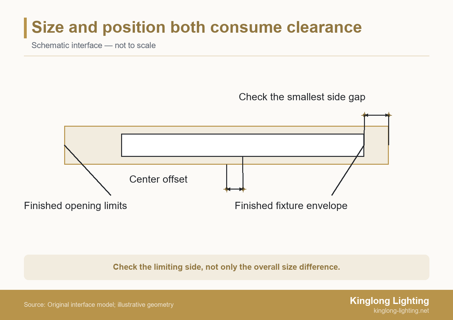
A gap calculation needs defined measurement endpoints and a direction. Autodesk’s stackup instructions start by selecting features that define the gap and establishing the stackup direction. For the following one-direction calculation, the endpoints are parallel opening and fixture edges; the model also allows a bounded relative center offset.
Consider this illustrative interface, not a Kinglong production specification. A finished opening is 610 ±3 mm wide, the finished fixture envelope is 590 ±2 mm wide and the relative center offset can be up to 4 mm in either direction. The project team chooses a minimum gap of 5 mm on each side for this example. All values are hypothetical; the fixture is assumed parallel to the opening, with other relevant effects already covered by the stated final-state bounds or separately assessed.
| Illustrative input | Nominal condition | Limiting condition for the smaller gap |
|---|---|---|
| Finished opening width, A | 610 mm | Smallest opening: 607 mm |
| Finished fixture width, B | 590 mm | Largest fixture: 592 mm |
| Relative center offset, e | 0 mm when centered | Up to 4 mm toward either side |
| Project-defined minimum gap | 5 mm per side | Example criterion, not an industry clearance rule |
The centered nominal gap is (610 − 590) ÷ 2 = 10 mm per side. That is not the limiting installation condition.
For this parallel-envelope model, the minimum gap is (Amin − Bmax) ÷ 2 − emax. Substituting the limits gives (607 − 592) ÷ 2 − 4 = 3.5 mm. The modeled interface misses the illustrative 5 mm criterion by 1.5 mm, even though each input stays within its own stated bound.
The division by two converts the overall width difference into a centered side gap. The center offset is then deducted in full from the limiting side. Do not deduct it from both overall widths or divide it by two. This arithmetic is a conservative bounds check within the stated model, not a probability of failure or a guarantee that every manufactured assembly will install.
Suppose the designer approves changing the opening to 620 ±3 mm while keeping the other inputs unchanged. The revised minimum gap becomes (617 − 592) ÷ 2 − 4 = 8.5 mm. That resolves the modeled gap shortage. The team would still verify the finished opening and assembled envelope against the revised drawing and confirm that the larger opening preserves the intended trim, appearance and installation access.
When Worst-Case Analysis Is More Useful Than RSS
For a one-off lighting interface with uncertain site variation, an explicit worst-case bounds check is often more useful than an attractive statistical result. It exposes whether the geometry can fail within the agreed limits. It does not require a claim about how frequently particular combinations occur.
Visual references have a different role. The published decorative lighting projects can help a team discuss form and architectural context, but a project image does not disclose the tolerance chain needed for a new installation.
Autodesk’s analysis documentation distinguishes simultaneous extreme limits in worst-case analysis from the statistical assumptions behind root-sum-square, or RSS, analysis. The methods answer different questions. RSS is not a way to erase a known site offset or to assume that unrelated contributors will cancel.
Statistical analysis can be useful when production distributions, dependencies and the chosen quality objective are understood. A decorative-lighting review may instead combine factory dimensions with a single constructed opening, installation positioning and hand-assembled materials. Without a justified model for those inputs, a calculated probability can look more precise than its evidence warrants.
Keep the physical scope equally clear. The example checks one direction with parallel boundaries. An irregular opening, tilted assembly or constrained insertion path can need a fuller geometry review. A positive side gap does not establish fastening access, maintenance space, structural adequacy or electrical suitability.
A Tolerance Stack Worksheet for the Design Review
Use the worksheet to record the final-state limits, measurement direction, evidence and usable adjustment for one defined interface. The factory completes product inputs; the site team completes constructed-opening and location inputs. Start with a drawing revision and shared datum, so that a later measurement does not silently change the model.
Copy these header fields into the review: interface name; drawing revision; measurement direction; shared datum; finished-state definition; functional minimum gap; reviewer and date. Complete the rows with real project values, not the illustrative numbers above.
| Contributor | Values to enter | Evidence and responsible team | How it enters the check |
|---|---|---|---|
| Finished opening | Nominal width; lower/upper limits; relevant sections | Finished-edge survey or controlled construction input; site team | Use the smallest usable width in the reviewed direction |
| Finished fixture envelope | Overall limits; glass orientation; finish and assembled-state definition | Assembly drawing and dimensional evidence; manufacturer | Use the largest included envelope; do not add included component limits again |
| Relative center position | Reference coordinates; permitted offset in each direction | Opening and suspension layout against shared datum; coordinated site/manufacturer input | Deduct the limiting relative offset from the relevant side gap |
| Suspension and vertical fit | Finished ceiling level; total drop; leveling and tilt constraints | Installation section and suspension detail; project team | Check separately where height or tilt affects the envelope |
| Usable adjustment | Direction; available travel; locked final position; access needed | Connection detail and assembly check; manufacturer and installer | Credit only movement that can actually be used and retained |
| Measurement basis | Method; instrument; conditions; relevant uncertainty; acceptance decision rule | Measurement record and calibration information; measuring team | Identify how confidence in the measured limit affects acceptance |
An unknown limit is an open input, not zero variation. Assign the missing measurement or confirmation before using that row to justify fabrication.
Measurement uncertainty is distinct from permitted product variation. NIST’s uncertainty guidance identifies instrument specifications and calibration reports among the information used in an evaluation. A tightly specified limit does not make a coarse measurement conclusive; agree how measurement uncertainty is handled when deciding acceptance near that limit.
If the worksheet exposes a need to change the canopy, envelope or opening, compare the visual and installation consequences as well as the price. The decorative lighting value engineering guide provides a related route for reviewing such alternatives.
Resolve the Tight Interface Before Fabrication
Resolve the contributor that consumes the missing clearance, then recheck the changed interface. Options include revising the opening, reducing the finished envelope, improving location control or designing accessible adjustment. The smallest-looking change is not necessarily the least disruptive: reducing a glass projection may alter the lighting composition, while enlarging a recess may affect trim coverage.
Ask the manufacturer which product dimensions can realistically be controlled and how they will be measured. Ask the contractor which finished dimensions and positions can be delivered on site. A tighter number written onto the drawing has no practical value until the responsible team can produce and verify it.
Then review the proposed correction through the installed condition. Does the adjustment remain available after the canopy is fitted? Can the connection be secured without shifting the fixture? Will the installer have access to the relevant fastener? If the proposal changes suspension geometry or support, send that change to the responsible engineer rather than treating extra movement as automatically acceptable.
For the illustrative enlarged-opening correction, verification would compare the measured finished opening and fixture envelope with the revised limits and confirm relative center position. An assembly check should test the relevant access and sequence as well. One successful trial can confirm that trial’s conditions; it does not establish that every permissible dimensional combination has been covered.
Send the dimensioned interface drawing, finished-opening references, completed worksheet, protected design features and unresolved site assumptions to Kinglong Lighting. Ask what the blueprint review can address and request clarification of open inputs and proposed dimension changes. Identify who will confirm the final site dimensions. This makes the development discussion specific without assuming that a supplier response is the project’s installation approval. Use those inputs to discuss the custom lighting interface.
Questions About Custom Lighting Tolerances
Can a general drawing tolerance cover every lighting interface?
No; a general tolerance only applies where the drawing says it applies, and critical fit interfaces may need separately agreed controls. Confirm which dimensions inherit the general note and which have individual limits. If the canopy fit or glass seating controls the installation, identify that relationship directly. Do not assume a general note also controls the contractor’s finished opening or suspension coordinates.
Does approving one glass sample prove replacement pieces will fit?
No; a visual sample approval does not by itself establish the dimensional interchangeability of replacement glass. Record the seating dimensions, orientation and relevant limits separately from color and texture approval. Clarify whether replacement pieces are interchangeable or matched to particular positions. Where matching is necessary, the replacement plan should preserve the identification and reference information needed to select the correct piece.
What if the finished ceiling opening cannot be measured yet?
Keep the interface provisional and agree how the final opening will be verified before the dependent dimensions are released. The team may develop the design around controlled construction inputs, provided their limits and responsibility are explicit. Identify which product dimensions can remain open and which would commit fabrication. Do not turn an estimated unfinished opening into a confirmed finished measurement.
Can the factory use millimeters while the site uses inches?
Yes, if the review uses a controlled unit system and records the conversion and rounding rules on the shared drawing. Retain the governing dimensions and units rather than repeatedly converting copied values between documents. Check limits as well as nominal sizes after conversion, especially when rounding consumes a small gap. Everyone comparing measurements should know which stated value governs acceptance.